A control valve is a tool that regulates fluid flow by altering the size of the flow passage depending on the signal from the controller. Control of the rate flow directly influences other factors like heat, density, concentration, stress, and the fluid level. The control valve is a type of mechanical flow meter that automatically sets stress or flow rate.
The flow control valves can work in all types of stress; if valves in a setup work in varying stress and heat, it is wise to pick Class 300 valves. It is a model to use the Class 300 valves in a set up unless the order uses valves with a rating less than Class 150. These valves keep the process parameters as close as possible to the desired levels.
See more: How Liquid Flow Sensor Works Accurate in Flow Measurement?
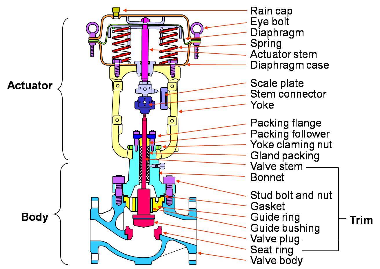
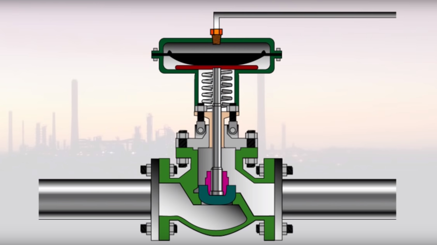
A mechanical flow meter usually sets the pace and is flanged for ease of use. The disk in the valve is moved by an actuator using a mechanical actuator. The valve runs the flow by moving a valve plug in bond to the ports within the valve. A valve plug is attached to a valve stem while the stem is linked to an actuator.
Main Parts of Flow Control Valve

A control valve has four key parts that make it work. The parts are the knob or actuator, the valve body, the positioner, and extras. The valve can be one of two types, a quarter-turn valve with the coned disk or cone is turned against a seat or a plug seat design where the plug is closed against the seat.
The valve is made of the trim parts and the bonnet assembly. The valve’s plan is meant to stand static fluid stress and differential stress to allow smooth fluid flow. It also provides tube connecting ends and supports the valve closure member and the sealing surfaces.
The actuator is designed to use either mechanical, pneumatic, hydraulic, or electric energy. The valves use the power to open and close the valve when activated. On the other hand, the position monitor controls the actuator’s movement to attain the set goal in the setup.
There are other extra parts on the mechanical flow meter that give life to the meter. The electro-pneumatic transducers act as transmitter and receiver of an electric signal to measure the fluid flow rate. On the other hand, pressure setters have a role in checking and setting the fluid’s stress level.
Know more: Aspects about a Roosa Master Injector Pump
Position indicators help the use of mechanical counters. These counters convert open and closed positions of the valve into electrical signals to ensure the exact status data sent to the control room.
How Control Valves Work?

The control valve is often a final control element in the firm’s control process. That means that it is a mechanical tool that manually changes the flow regarding changes in setting goals. The valve sets the flow of fluids such as water, steam, gas, and chemical compounds to make up for the load upset and keep the flow as close it can to the set goals.
Though control valves are crucial, they are often the most run-down part of the control loop. That boils down to most technicians don’t get the facets and terms in fluid control of the valves. For a good use of the valve, it is wise to know the deep working of the tools and flow such as metallurgy, noise control, piping, and fluid mechanics.
The control valve has a sensor, a transmitter, and a controller that matches the set goals parameter received from the control valve. If the results are not the same, the controller sends a rectification signal to the final control element. The final control element is what keeps the system in order.
The sensors act as senses or eyes to the set up while the controller acts as the control loop’s brain. As simple as it is, it is still shrouded in mystery and is often misunderstood. But you can’t blame the folks who don’t see these functions as most of the functions can be set by a remote computer system, leading to neglect of the hardware system.
Types of Control valves
There are many flow control valves; thus, to get around, it’s good to classify them for easy understanding. There are five main ways of valve control. They are classification:
Based on pressure drop
High recovery valves regain most of the static pressure drop from the inlet to the vena contract. These types of valves have lower recovery coefficients. They include the ball valve, The plug valve, and the gate valve.
Low recovery valves regain low levels of the static pressure drops from the inlet to the outlet. Unlike the high recovery valves, these valves have high recovery coefficients. They include globe valves and angle valves.
Learn more: How Does Pneumatic Valve systems Works?
Based on the movement profile
First, we have the sliding system where the plug or valve stem moves in linear motion. Example of these plugs is the Globe valve, the angle valve, and the rotary valve.
Rotary valves, on the other hand, have valve disks that undergo rotary motion. The example includes the ball valve and the butterfly valve.
Cons of Control valves
It is no secret that the control valve is the best mechanical flow meter. There is also a point when the tools fail due to some grave issues. Some of the issues that you check out for are:
Most of the valves are large and are overkill for small setups. Very large valves are often costly and a waste of cash as they are not aware of fine-tuning when needed. Funny enough, most valves are often two lines huger than the pipe.
Sensor often faces long lags. That implies that the sensors take a long time before reacting to flow. The lag is caused by the sensor being located too far away.
The flow valve can be sticky if product leakage causes them to bind to the stem or if cram is taut. At some point, there may be a low air supply or leakage, leading to a small force to move the stem.
Conclusion:
Control meters have eased the mastery of different elements of fluids in an order. Installation of a mechanical flow meter ensures that you set the flow rate and factors like stress, heat, and pressure.


Leave a comment